INTRODUCTION
Like their pipeline counterparts, Borosilicate glass column components find universal
application throughout the world’s chemical, pharmaceutical, food and drink and
allied industries where the advantage of using glass as a basis for the construction of
complete process systems have long been recognized:
With almost universal resistance to
corrosion, a long service life is guaranteed and maintenance is kept to a minimum.
Their transparency permits visual
monitoring of the process at all times.
Being inert, the risk of contamination
is negligible.
Smooth surfaces allow easy cleaning and
sterilization and prevent the build-up of solid on the inner walls.
In many unit operations such as reaction,
extraction and absorption, the transparency factor of glass column components is a
particular advantage. As an example, colour changes in reaction processes are easily
monitored, droplet separation in extraction processes can be observed unhindered and
constant visual monitoring of hydraulic performance in packed columns is possible.
Column components are available from DN 80 to DN 450 with a smaller range of precision
bore components available from DN 25 to DN 150 for specific applications where close
internal tolerances are essential.
The complete range of column components is described on the following pages. All column
components have standard flat buttress end connections. Further details of theses are
provided in section: Technical Information.
For standard flat buttress end connections from DN25 to DN300, it is possible to achieve a
3° deflection in the joint by using a flexible gasket. Details of these and all other
couplings and gasket can be found in section Couplings.
DN refers to the nominal bore. Unless otherwise stated all dimensions are given in mm.
For permissible operating conditions, unless otherwise stated in the individual
description, please see section Technical Information.
top
Applications
of internals
Columns used for reaction, absorption and
extraction processes can be fitted with many different internals such as packed beds,
structured packing and sieve or bubble-cap trays. The typical operating characteristics,
as well as the recommended and possible areas of application for each of these internals,
are detailed in this section: the processes beuing limited to gas/liquid operation in the
form of rectification and absorption processes.
Packed beds or structure packing are used to create the
surface required for mass transfer by increasing the area of contact at the surface of the
liquid when it flows over the internals as a film. Irregular packed beds have a relatively
high pressure drop. Figure 1 shows the pressure drop for ceramic saddles . a very
significant reduction in pressure drop, particularly in regard to vacuum rectification,
can be achieved by the introduction of structured packing. Figure 2, for example shows the
pressure drop values for SULZERKERAPAK. A clear reduction in pressure drop is discernible
here.
Applications of internals
In plate columns the boundary surface for mass transfer is
created by the liquid phase flowing across the trays being penetrated by the gas or vapour
rising from the plate below. The main distinctions here are between bubble cap trays and
sieve trays. Plate columns have higher pressure drop then packed columns. To illustrate
this, Figure 3 on the previous page shows the pressure drop of the buyer low-rise tray.
The pressure drop of the tray is about the same as for 1 meter packing of 25mm ceramic
saddles.
The suitability of internals to a particular process is really determined by the process
conditions in each case. If a low pressure drop is required, then structured packing are
the main ones to choose. In all other cases the permissible operating range of the various
internals for a particular application is the determining factor. Packed and plate columns
have different operating ranges as a result of the different type of boundary surface
creation. The terms operating range here refers to the range of gas and liquid flows
within which problem-free operating of the column is possible.
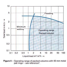
Figure 4 shows typical load characteristics of a packed column with the operating range
shaded. This is mainly limited by the so-called upper load limit, designated by flooding,
against higher flow. The lower load limit designated by minimum wetting stems from the
requirements that the packing has to have an even film of liquid to achieve the desired
separation. It can also be seen from Figure 4 that it is possible to individual cases,
however, the achievable separation effect should be checked.
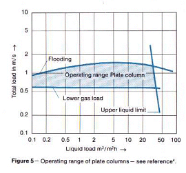
Plate columns have different operating characteristics. As the load characteristics in
Figure 5 show, several factors limiting the operating range have to be taken into
consideration with this design. It must be emphasized in particular that turndown of the
liquid load is much greater for the plate column.
|
|
top
Column
Sections
DN
(mm) |
L
(mm) |
Volume
(L) |
Volume
Stacked
Rings (L) |
Free
Area |
Minimum
Packing
Diameter
(mm) |
Maximum
weight of
packing
(kg) (lbs) |
 |
80 |
1000 |
4 |
|
50% |
7 |
20 |
45 |
100 |
1000 |
8 |
|
60% |
10 |
30 |
65 |
150 |
1000 |
16 |
|
65% |
15 |
60 |
130 |
225 |
1000 |
32 |
|
75% |
20 |
90 |
200 |
225 |
1500 |
51 |
|
75% |
20 |
90 |
200 |
300 |
1000 |
60 |
|
75% |
25 |
150 |
330 |
300 |
1500 |
95 |
|
75% |
25 |
150 |
330 |
450 |
1500 |
186 |
14 |
75% |
25 |
250 |
550 |
The figures in liters
are the volumes available for packing above the supports or, Where applicable, above the
two rows of stacked rings.
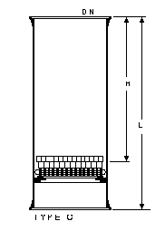
Columns are fundamental to many process plants and a range of column components in
borosilicate glass is available in nominal bores up to 1000mm.
Column
Sections
DN
(mm) |
L
(mm) |
DN1
(mm) |
L1
(mm) |
H
(mm) |
Type |
Cat. Ref. |
|
80 |
1000 |
|
|
900 |
A |
GCS3/1000 |
80 |
1000 |
25 |
80 |
850 |
B |
GCST3/1000 |
100 |
1000 |
|
|
880 |
A |
GCS4/1000 |
100 |
1000 |
25 |
85 |
850 |
B |
GCST4/1000 |
150 |
1000 |
|
|
845 |
A |
GCS6/1000 |
150 |
1000 |
25 |
100 |
845 |
B |
GCST6/1000 |
225 |
1000 |
|
|
845 |
A |
GCS9/1000 |
225 |
1000 |
25 |
100 |
845 |
B |
GCST9/1000 |
225 |
1500 |
|
|
1345 |
A |
GCS9/1500 |
225 |
1500 |
25 |
100 |
1345 |
B |
GCST9/1500 |
300 |
1000 |
|
|
840 |
A |
GCS12/1000 |
300 |
1000 |
25 |
100 |
840 |
B |
GCST12/1000 |
300 |
1500 |
|
|
1340 |
A |
GCS12/1500 |
300 |
1500 |
25 |
100 |
1340 |
B |
GCST12/1500 |
450 |
1000 |
|
|
820 |
C |
GCS450/1000 |
450 |
1500 |
|
|
1320 |
C |
GCS450/1500 |
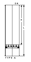
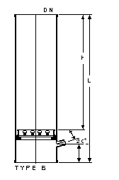
Column sections are
supplied complete with the appropriate size of packing support. In type C columns, two
rows of stacked glass Ranching rings immediately above the support provide a firm base on
which the dumped packing is supported.
Type C column sections can be supplied with a side branch (for example for thermometer
pocket) on special order. This is located near the top of the column section.
top
Packing Supports
DN
(mm) |
L
(mm) |
Free
Area |
Maximum
Load
(kg) (lb) |
Minimum
Packing
Diameter
(mm) |
Type |
Cat Ref |
 |
80 |
15 |
50% |
20 |
45 |
7 |
A |
GLB3 |
100 |
20 |
60% |
30 |
65 |
10 |
A |
GLB4 |
150 |
30 |
65% |
60 |
130 |
15 |
A |
GLB6 |
225 |
30 |
75% |
90 |
200 |
20 |
A |
GLB9 |
300 |
30 |
75% |
150 |
330 |
25 |
A |
GLB12 |
450 |
70 |
75% |
250 |
550 |
25 |
B |
GHD450 |
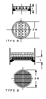
Type A supports are
glass
Type B supports are glass and PTFE
Glass packing supports
are supplied as part of the column section assembly. They are normally only ordered
separately when required as replacements.
They are seated on a PTFE crescent ring which is supplied with the support. Two rows of
stacked glass rings are also supplied with type B supports.
top
Perforated Plates
DN
(mm) |
L
(mm) |
Free
Area |
Type |
Material |
Cat Ref |
 |
80 |
11 |
22% |
A |
glass |
GCP3 |
100 |
16 |
30% |
B |
glass |
GCP4 |
150 |
16 |
30% |
B |
glass |
GCP6 |
225 |
16 |
37% |
B |
glass |
GCP9 |
300 |
16 |
32% |
B |
glass |
GCP12 |
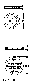
These plates are fitted
at the top of columns as restrainers for column packing where there is a risk of damage to
other parts of the installation.
They are clamped between buttress ends and a gasket is required on each side. Longer bolts
than usual are required in the flanges used with the glass plates.
top
Support Ring, TFE-Covered
DN
(Glass)
(mm) |
D
(O.D.)
(mm) |
D1
(I.D.)
(mm) |
D2
(Gasket)
(mm) |
D3
(Bolt
Circle)
(mm) |
Holes
(No./
Size)
(mm) |
L
(Thickness)
(mm) |
Cat Ref |
 |
150 |
260 |
102 |
194 |
241 |
8/11 |
11 |
GTCSR6 |
225 |
343 |
194 |
267 |
310 |
8/11 |
11 |
GTCSR9 |
300 |
419 |
244 |
349 |
394 |
12/11 |
11 |
GTCSR12 |
450 |
616 |
397 |
540 |
584 |
12/14 |
11 |
GTCSR450 |
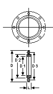
This support ring is
made of steel covered with a TFE machined envelope over a compressed fiber gasket. Clamp
the support ring between two column sections. For 225 mm size and over, we recommend using
a TFE Crescent Ring Gasket (Cat. Ref. TR) on each side of the plate. This makes it easier
to get a tight seal, and you can reuse the support ring when you wish.
The ring supports either the ceramic packing support plate or the ceramic distributor
plate. This ring lets you remove an entire packed section without having to remove the
packing first.
For bromine service please check with GARG.
top
Packing Support Plate, Ceramic
DN
(Column)
(mm) |
D
(Plate)
(mm) |
L
(mm) |
Minimum
Packing
Size
(mm) |
Cat Ref |
 |
225 |
216 |
114 |
10 |
GPSP9 |
300 |
292 |
114 |
13 |
GPSP12 |
450 |
438 |
178 |
13 |
GPSP450 |
Plates are made from
white unglazed chemical porcelain in the riser-type "gas injection" design. All
ceramic plates have greater than 50% free area. All sizes of these plates can easily
accommodate a 3-meter (10 ft) height of any conventional packing material. Consult
GARG
Process Systems about heights greater than this.
To install these plates, center one on top of a TFE-covered support ring; then raise the
plate and ring together to meet the column section above. The ceramic plate stays on the
edge completely inside the column. Caution: do not try to slide the ceramic plate down
from the top of the column section--it may get stuck.
top
Distributor Plate, Ceramic
DN
(Column)
(mm) |
D
(mm) |
D1
(mm) |
L
(mm) |
Flow Rate
Range
(L/hr.) |
Cat Ref |
 |
150 |
127 |
140 |
76 |
170-450 |
GLD6M |
225 |
203 |
215 |
89 |
510-1130 |
GLD9M |
300 |
229 |
290 |
89 |
680-1590 |
GLD12M |
450 |
356 |
445 |
133 |
1590-3630 |
GLD450 |
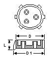
This plate is made in
one piece from white unglazed chemical porcelain. The gas risers in the center of the
plate effectively reduce the pressure drop across the plate and so retard velocity so as
to lower the hydraulic gradient effect on the liquid, thereby giving more uniform liquid
distribution.
For smaller-size distributor plates, simply use a glass packing support plate (in this
catalog). For distributor plates capable of handling either lower or higher flow rate
ranges, check with GARG Process Systems for plates available on special order.
top
Raschig Rings
Size
(mm) |
kg/
liter |
Packing
Factor
(F) |
m2/m3 |
Cat Ref |
 |
8 x 8 |
0.68 |
700 |
500 |
GFC8 |
10 x 10 |
0.58 |
530 |
450 |
GFC10 |
15 x 15 |
0.44 |
300 |
300 |
GFC15 |
20 x 20 |
0.28 |
220 |
280 |
GFC20 |
25 x 25 |
0.27 |
145 |
200 |
GFC25 |
40 x 40 |
0.29 |
90 |
160 |
GFC40 |
50 x 50 |
0.320 |
65 |
120 |
GFC50 |
One standard type of
glass column packing is available: Raschig rings. It is especially suitable for use in
glass columns because of its low bulk density.
Selection and use of
column packing
1. The ratio of column diameter to packing diameter should not be less than 8:1.
2. Where smaller sizes of packing are used, it is sometimes advisable to use a small layer
of larger packing immediately above the support to prevent the smaller packing falling
through.
3. In vacuum operations and applications involving high vapor velocities glass
packing--because of its low weight--may tend to be lifted away from the top of the column
sections and may cause damage to other parts of the installation. This can be prevented by
fitting a suitable form of restraint (for example a perforated plate) above the column
section.
4. Various methods can be used for the random distribution of packing in a column. One
method is to fill the column section with water, then dump in the packing. If this is
used, care must be taken not to exceed the maximum pressure permissible in the
column.
5. Column packings other than the standard glass ones can be used but bulk density should
be taken into consideration and the maximum permissible load on the support should not be
exceeded.
top
Precision Bore Pipe Sections
DN
(mm) |
D1
(mm) |
L
(mm) |
L1
(mm) |
Cat Ref |
 |
25 |
25.4 |
1000 |
900 |
GPPS1/1000 |
40 |
38.0 |
1000 |
890 |
GPPS1.5/1000 |
50 |
47.3 |
1000 |
880 |
GPPS2/1000 |
80 |
72.45 |
1000 |
870 |
GPPS3/1000 |
100 |
100.4 |
1000 |
840 |
GPPS4/1000 |
150 |
152.4 |
1000 |
820 |
GPPS6/1000 |
L1 is the approximate
length of the precision bore zone of the pipe. The bore of the remaining pipe is not less
than the minimum bore of the precision zone. Where the inside diameter of a column must be
within closely controlled limits (for example to accommodate sieve plate assemblies),
precision bore pipe sections are used.
top
PTFE Redistributors
DN
(mm) |
d
(mm) |
Type |
Cat Ref |
 |
80 |
55 |
A + B + C |
GTLCF3 |
100 |
80 |
A + B + C |
GTLCF4 |
150 |
100 |
A + B + C |
GTLCF6 |
225 |
175 |
A + B + C |
GTL9 |
300 |
215 |
A + B + C |
GTL12 |
450 |
365 |
A + B + C |
GTL45 |
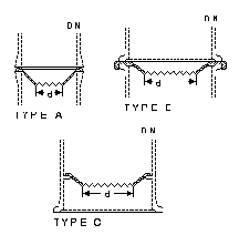
DN is the nominal bore
of the column in which the redistributor is used Type A and Type B redistributors are
clamped between buttress ends and no gasket is required. Type C redistributors fit between
the packing support and the glass shelf built into the column section.
top
Liquid Seal
DN
(mm) |
DN1
(mm) |
L
(mm) |
L1
(mm) |
Cat Ref |
 |
25 |
25 |
160 |
205 |
GLS1 |
40 |
25 |
315 |
305 |
GLS1.5 |
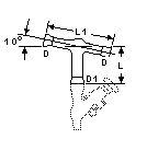
This device prevents
vapors from passing directly into the after cooler and receiver. Install it on the product
exit line from the reflux splitter, which also has a 10° pitch. A valve branch DN1
permits sampling and draining. Glass Valves are covered in another section of this
catalog.
top
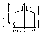
Column Adaptors
DN
(mm) |
DN1
(mm) |
DN2
(mm) |
L
(mm) |
L1
(mm) |
L2
(mm) |
Cat Ref |
|
80 |
25 |
25 |
178 |
95 |
90 |
GCA
3/1/1 |
80 |
40 |
25 |
178 |
108 |
90 |
GCA
3/1.5/1 |
100 |
25 |
25 |
203 |
108 |
102 |
GCA
4/1/1 |
100 |
40 |
25 |
230 |
121 |
102 |
GCA
4/1.5/1 |
100 |
40 |
40 |
230 |
121 |
102 |
GCA
4/1.5/1.5 |
100 |
50 |
25 |
228 |
127 |
127 |
GCA
4/2/1 |
100 |
50 |
40 |
228 |
127 |
127 |
GCA
4/2/1.5 |
150 |
40 |
25 |
356 |
140 |
229 |
GCA
6/1/1.5 |
150 |
50 |
25 |
356 |
152 |
229 |
GCA
6/1/2 |
150 |
25 |
40 |
241 |
146 |
127 |
GCA
6/1.5/1 |
150 |
40 |
40 |
241 |
146 |
127 |
GCA
6/1.5/1.5 |
150 |
50 |
40 |
254 |
146 |
127 |
GCA
6/1.5/2 |
150 |
40 |
50 |
241 |
152 |
127 |
GCA
6/2/1.5 |
150 |
50 |
25 |
241 |
152 |
127 |
GCA6/2/1 |
150 |
50 |
50 |
254 |
152 |
127 |
GCA
6/2/2 |
150 |
80 |
25 |
254 |
165 |
127 |
GCA
6/3/1 |
150 |
100 |
25 |
305 |
203 |
152 |
GCA
6/4/1 |
225 |
40 |
25 |
330 |
184 |
152 |
GCA
9/1.5/1 |
225 |
50 |
25 |
330 |
190 |
152 |
GCA
9/2/1 |
225 |
100 |
25 |
406 |
241 |
228 |
GCA
9/4/1 |
225 |
40 |
40 |
330 |
184 |
152 |
GCA
9/1.5/1.5 |
225 |
50 |
40 |
330 |
190 |
152 |
GCA
9/2/1.5 |
225 |
80 |
40 |
406 |
203 |
228 |
GCA
9/3/1.5 |
225 |
100 |
40 |
406 |
241 |
228 |
GCA
9/4/1.5 |
225 |
150 |
40 |
406 |
267 |
228 |
GCA
9/6/1.5 |
225 |
50 |
50 |
355 |
190 |
152 |
GCA
9/2/2 |
225 |
100 |
50 |
432 |
241 |
228 |
GCA
9/4/2 |
300 |
40 |
25 |
381 |
222 |
190 |
GCA
12/1.5/1 |
300 |
40 |
40 |
381 |
222 |
190 |
GCA
12/1.5/1.5 |
300 |
50 |
40 |
381 |
229 |
190 |
GCA
12/2/1.5 |
300 |
80 |
40 |
432 |
241 |
228 |
GCA
12/3/1.5 |
300 |
100 |
40 |
432 |
279 |
228 |
GCA
12/4/1.5 |
300 |
150 |
40 |
432 |
305 |
228 |
GCA
12/6/1.5 |
300 |
50 |
50 |
406 |
229 |
190 |
GCA
12/2/2 |
300 |
80 |
50 |
432 |
241 |
228 |
GCA
12/3/2 |
300 |
100 |
50 |
432 |
279 |
228 |
GCA
12/4/2 |
300 |
150 |
50 |
432 |
305 |
228 |
GCA
12/6/2 |
450 |
50 |
25 |
711 |
305 |
381 |
GCA
18/2/1 |
450 |
150 |
50 |
711 |
381 |
381 |
GCA
18/6/2 |
450 |
225 |
50 |
762 |
406 |
381 |
GCA
18/9/2 |
top
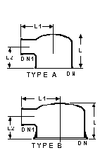
Column Adaptors - Flat Top
DN
(mm) |
DN1
(mm) |
L
(mm) |
L1
(mm) |
L2
(mm) |
Type |
Cat Ref |
 |
150 |
40 |
155 |
165 |
110 |
A+B |
GFH 6/1.5 |
225 |
40 |
165 |
200 |
120 |
A+B |
GFH 9/1.5 |
300 |
40 |
190 |
240 |
140 |
A+B |
GFH 12/1.5 |
450 |
40 |
285 |
300 |
175 |
A+B |
GFH 450/1.5 |
top
Column Feed Pipes
DN
(mm) |
DN1
(mm) |
DN2
(mm) |
d
(mm) |
L
(mm) |
L1
(mm) |
Cat Ref |
 |
80 |
40 |
25 |
13 |
100 |
115 |
GFP 3 |
100 |
40 |
25 |
13 |
125 |
115 |
GFP 4 |
150 |
40 |
25 |
13 |
150 |
115 |
GFP 6 |
225 |
40 |
25 |
13 |
185 |
115 |
GFP 9 |
300 |
40 |
25 |
13 |
230 |
115 |
GFP 12 |
450 |
80 |
40 |
25 |
320 |
150 |
GFP 450 |
DN is the nominal bore
of the column in which the feed pipe is used. PTFE/Steel Construction
These feed pipes have a fused-in distribution tube which directs the process fluid down
onto the center of the column packing. They are designed for use with unequal tee pieces .
top
Resistance Thermometers
DN
(mm) |
d
(mm) |
L
(mm) |
L1
(mm) |
Cat Ref |
 |
25 |
12 |
250 |
100 |
GWT 1/100 |
25 |
12 |
290 |
140 |
GWT 1/140 |
25 |
12 |
430 |
280 |
GWT 1/280 |
40 |
12 |
295 |
140 |
GWT 1.5/140 |
40 |
12 |
555 |
400 |
GWT 1.5/400 |
40 |
12 |
705 |
550 |
GWT 1.5/550 |
Non-standard lengths
can be supplied to special order.
Resistance thermometers are used for remote indication, recording and control of
temperature of gases and liquids. They can be connected to all conventional types of
instruments which work on a basic nominal resistance of 100 ohms.
GARG resistance thermometers consist of a platinum resistance element in a borosilicate
glass sheathe with a perforated glass guard to ensure additional protection from
mechanical damage to the element. The sealed-in element is in direct thermal contact with
the fluid.
top
Thermo well, Single-End
DN
(mm) |
D1
(mm) |
D2
(mm) |
L
(mm) |
Cat. Ref. |
 |
40 |
16 |
10 |
70 |
GTWS1/1 |
40 |
19 |
13 |
70 |
GTWS1/2 |
40 |
25 |
16 |
70 |
GTWS1/3 |
50 |
16 |
10 |
70 |
GTWS2/1 |
50 |
19 |
13 |
70 |
GTWS2/2 |
50 |
25 |
16 |
70 |
GTWS2/3 |
75 |
16 |
10 |
89 |
GTWS3/1 |
75 |
19 |
13 |
89 |
GTWS3/2 |
75 |
25 |
16 |
89 |
GTWS3/3 |
These thermo wells are
made to order. Please specify the length up to 914mm (36") when ordering.
top
Thermo well, Double-End
DN
(mm) |
D1
(mm) |
D2
(mm) |
L
(mm) |
Cat Ref |
 |
40 |
16 |
10 |
150 |
GTWD1/1 |
40 |
19 |
13 |
150 |
GTWD1/2 |
40 |
25 |
16 |
150 |
GTWD1/3 |
50 |
16 |
10 |
150 |
GTWD2/1 |
50 |
19 |
13 |
150 |
GTWD2/2 |
50 |
25 |
16 |
150 |
GTWD2/3 |
75 |
16 |
10 |
150 |
GTWD3/1 |
75 |
19 |
13 |
150 |
GTWD3/2 |
75 |
25 |
16 |
150 |
GTWD3/3 |
Double-end thermo wells
are especially useful for sealing out the atmosphere.
These thermo wells are made to order. Please specify the length up to 914mm (36")
when ordering.
top
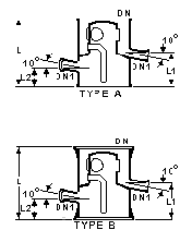
Reflux Separators - Manually Operated
DN
(mm) |
DN1
(mm) |
L
(mm) |
L1
(mm) |
L2
(MM) |
Cat Ref |
 |
80 |
25 |
190 |
115 |
82 |
GRDA3 |
100 |
25 |
255 |
145 |
95 |
GRDA4 |
150 |
25 |
255 |
145 |
100 |
GRDA6 |
225 |
25 |
380 |
150 |
115 |
GRDA9 |
300 |
25 |
380 |
150 |
110 |
GRDA12 |
450 |
40 |
610 |
275 |
150 |
GRDA18 |
On this type of reflux
separator, a valve is fitted to the outlet pipe. When it is open the condensate flows only
through the product off-take connection, but it can be partially or fully closed so that
some or all of the condensate returns to the column as reflux giving coarse reflux
control.
FLOW DATA
Cat Ref |
Minimum cross
sectional area
available for
vapor flow
cm2 |
Maximum Rate
of liquid product
or reflux expressed
as water at 20°C
liters/hour |
GRDA3 |
10 |
300 |
GRDA4 |
20 |
475 |
GRDA6 |
40 |
700 |
GRDA9 |
150 |
900 |
GRDA12 |
170 |
1100 |
GRDA450 |
670 |
1500 |
top
Reflux Separators - Automatically Operated
In applications where
there is need for the reflux to be at a fixed value, then it is advisable to fit an
electro-magnetically or pneumatically operated reflux separator in conjunction with a
timer.
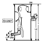
Reflux Separators - Magnetically Operated
This type of reflux
separator uses a swinging funnel mechanism. The funnel, which has a soft iron core sealed
into it, is operated magnetically from outside the column so that the condensate can be
removed from the column and reflux returned to the column in correct ratio. Activation of
the electromagnet moves the funnel into the off-take position.
The electromagnet (shown dotted) and timer should be ordered separately. Details can be
found below.
DN
(mm) |
DN1
(mm) |
L
(mm) |
L1
(mm) |
L2
(mm) |
Cat-Ref |
 |
80 |
25 |
380 |
75 |
75 |
GRHM3 |
100 |
25 |
455 |
90 |
90 |
GRHM4 |
150 |
25 |
455 |
90 |
90 |
GRHM6 |
225 |
25 |
560 |
100 |
100 |
GRHM9 |
300 |
25 |
685 |
140 |
430 |
GRHM12 |
Flow Data
Cat-Ref |
Minimum free
cross-section
for vapors
(cm2 ) |
Maximum distillate
volume in relation
to water at 20°C
(l/h) |
GRHM3 |
10 |
90 |
GRHM4 |
20 |
180 |
GRHM6 |
40 |
300 |
GRHM9 |
150 |
525 |
GRHM12 |
170 |
675 |
top
Electromagnets
For use with RHM reflux
separators, the RPA electromagnet can be used in hazardous areas and is certified as (Ex)s
G5 in Germany.
Operating Voltage: 24V DC
Operating Current: 0.5A
They are mounted off the main tubular support structure using the adjustable fitting
supplied. They should be located just clear of the glass and lined up with the marks on
the body of the reflux separator.
Electromagnets
top
Electronic Timers
These electronic timers
are designed for use in conjunction with type RPA electromagnets shown above and
magnetically operated reflux separators.
The timer allows variations of reflux and take-off in the ration 1/99/1.
Standard Operating voltage 240V, 1ph, 50Hz.
A flameproof version of
this timer is also available. This is housed in an explosion proof enclosure EEXd IIB T6
(III A Class) and allows variations of reflux and take-off in the ration 1/100/1.
|


