Search Text                                            Technical Info

Home | Profile | Quality | Technical Info | Products | Standard Assemblies | Laboratory GlasswareGlass Jacketed Vessels | Glass Tubes | PTFE Lined Products | PTFE Labware | Plastic Labware | Contact Us |Feedback | Sitemap


Properties Of Borosilicate Glass Per. Operating Temperature
Chemical Composition Permissible Operating Pressure 
Chemical Resistance  Per. Operating Conditions 
Physical Properties Buttress Ends 
Optical Properties  Working Temperatures 
Mechanical Properties  English Metric Conversions
Permissible Operating Conditions  Jacketed Components


Properties Of Borosilicate Glass


The advantage of using glass process plant and pipeline components as a basis for the construction of complete process systems have long been recognized throughout the world’s chemical, pharmaceutical, food and drink and allied industries. 

All the glass components detailed in this catalogue are manufactured exclusively from borosilicate glass type 3.3. Its principal features are its almost universal resistance to corrosion and its low coefficient of thermal expansion which allows great thermal strength and resistance to thermal shock.

Borosilicate glass plant and pipeline is used in both internal pressure and vacuum applications.

All the glass components in this catalogue comply with ate above specifications. In addition, components with butteress ends DN 25 to DN 450 comply with the dimensional and wall thickness requirements of ISO 3585.

For information on the testing, handling and use of glass plant, pipeline and fitting, please refer to ISO 3586.


TOP 


Chemical Composition

The borosilicate glass used in the manufacture of our range of process plant and pipe line components  has the following approximate composition.  

Component % by weight
SiO² 80.6  
B²O³ 12.5  
Na²O  4.2  
Al²O³  2.2  
Others  0.5  

TOP 


Chemical Resistance

Borosilicate glass is resistant to almost all substances except hydrofluoric acid, phosphoric acid and hot strong caustic solutions. Of these, hydrofluoric acid has the most serious effect and, even when a solution contains a few parts per million, corrosion will occur. 

Phosphoric acid and caustic solution cause no problem when cold but at elevated temperatures corrosion occurs. Caustic solution up to 30% concentration can be handled safely at ambient temperature. Under actual service conditions, the effect of turbulence and traces of other chemical is the solution may increase or decrease the rate of attack. Therefore, it is not possible to give precise figure for corrosion by caustic solutions, but Figure 1 shows typical rates.

TOP  


Physical Properties

Coefficient of mean linear thermal expansion

(20°C to 300°C)                     a = (3.3 ± 0.1) x 10-6 k –1

Mean thermal conductivity

(20°C to 200°C)                     l = 1.3 W/mK

Mean specific heat capacity

(20°C to 200°C)                     Cr = 910 j/kgk

Density  at 20°C                   u = 2.23 g/cm³

TOP  


Optical Properties

With borosilicate glass, the transmission of ultra-violet light – which is the great importance for photo-chemical reaction- is somewhat greater in the middle spectrum that with normal window glass.

If photosensitive substances are being processed, the glass can be amber stained to special order. This permanent coating reduces the ultra violet light transmission to a minimum. Figure 2 shows a comparison of the light transmission for plain and amber glass.  

TOP  


Mechanical Properties

The mechanical properties of the glass differ from those of metals. The lack of ductility of the glass prevent the equalization of stresses at local  irregularities or flaws and the breaking strength varies considerably.

Whilst the average breaking tensile stress of borosilicate  glass with flawless fire polished surface is approximately 70N/mm² the allowable design stress is considerably lower. AD-N4 specifies the allowable design stress in tension, bending and compression taking into account the likely glass surface condition in service

In addition the thermal stresses resulting from differential expansion of the inner and outer glass surface must be considered.  

TOP  


Permissible Operating Conditions

Thermal Shock  

The permissible values for working temperature and    pressure must always be considered together as thermal stresses  resulting from high temperature differences between the inner and outer glass surfaces reduce the permissible working pressure (see Figures 3 to 8).

If  the  internal temperature is less than the external - For example: in low temperature applications or for vessels with external heating – the thermal stresses require detailed consideration and we recommend that our Technical Department is consulted.  

TOP  


Permissible Operating Temperature

Borosilicate glass retains its mechanical strength and will deform only at temperature which approach its strain point, approximately 510°C. The permissible operating temperature is, however, considerably lower – normally at about 200°C – for glass components, provided that there is no temperature shock.

In exceptional circumstances, higher temperatures can be achieved possibly up to 300°C  (see AD-N4). However, additional precautions are required and we recommend that our technical department is again consulted.

At sub-zero temperatures, the tensile strength of borosilicate glass tends to increase and equipment can be used at temperatures as low as -50°C.

These temperature limits should be regarded only as a guideline and must always be modified in accordance with the actual operating conditions in any given application. The individual operating condition of some of the components detailed in this catalogue must also be considered. Where such operating limits apply, they are detailed in the individual catalogue section and component description

Under normal operating conditions, rapid changes in temperature should be avoided as this will result in increased stress in the glass. Experience has shown however that under exceptional conditions, a degree of thermal shock can be tolerated.

It is undesirable to give an overall figure but, as a general guide, sudden temperature change of up to around 120°C can be accommodated.  

TOP  


Permissible Operating Pressure

The maximum permissible operating pressure and the reduction in permissible pressure with increasing temperature difference between the process and ambient (Du) are shown in figure 3 to 8. Figure 3 and 4 are valid for all glass components with the exception of valves and filters (see figure 5 and 6), spherical vessels (see figure 7 and 8) and heat exchanger internal (see section 5 - Heat Exchangers).

Depending on the shape and working conditions, glass components can be used, under certain circumstance, at higher internal pressure. In these cases, the component will be marked in accordance with AD-N4.

Unless otherwise stated all standard glass components are suitable for operating at full vacuum subject to the temperature limits shown in Figure 3 to 8

In cases where glass in operated under a gas pressure or vacuum we are recommend that our technical department is consulted for further information on suitable external protection.  

TOP  


Permissible Operating Conditions


Typical External Heat Transfer Co-efficient.

Location Installation aa (W/m²K)  
Door  Insulated 2.3  
Protected by screens 5.8  
Exposed to draught  11.6 
Outdoor  Insulated 2.3  
Protected by screens  11.6  
Exposed to draught 58.0  

TOP  


Buttress Ends

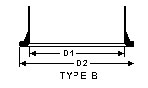
The glass process plant and pipeline components detailed in this catalogue have either standard flat buttress ends (Type A + B from DN 25  to  DN  450)

The following table provides dimensional information on standard flat buttress ends form for the range of glass components detailed in this catalogue.

Nominal Bore

DN

mm

25

40

50

80

100

150

225

300

450

Diameter

D1

mm

26.5

38.5

50

76

104

154

229

308

462

Diameter

D2

mm

42

57

69

99

132.5

185

258

340

535

         Type

A        +        B


Ti10.jpg (2035 bytes)

Maximum Working Pressures

Depending on shape and working conditions, glass components can be used, under certain circumstances, at higher internal pressures.

Although bar is a measure of absolute pressure, throughout these pages the figures given for maximum recommended working pressure represent pressures above atmospheric; i.e., "gauge" pressure.

Please Note:

Because of the potential energy of gases under pressure, we recommend you specify and provide safeguards for equipment and personnel in the unlikely event of a systems failure. For the same reason, pressurized as should not be used to test a system.

All sizes are safe for use under full vacuum.

DN

Bar

PSI


25

7.0

100

40

4.5

65

50

4.0

58

80

3.0

43.5

100

2.5

36.2

150

2.0

29

225

1.0

14.5

300

0.7

10.2

450

0.5

7.3


TOP  


Working Temperatures

Borosilicate glass retains its mechanical strength and will deform only at temperatures which approach its strain point. The practical upper limit for operating temperatures Is much lower and is controlled by the temperature differentials in the glass, which depend on the relative temperatures of the contents of the equipment and the external surroundings.

provided borosilicate glass is not subjected to rapid change in temperature, creating undue thermal shock, it can be operated safely at temperatures up to 4500F (2320C). The normal limiting factor is actually the gasket material. The degree of thermal shock (usually defined as sudden chilling) which it can withstand depends on many factors, for example: stresses due to operating conditions; stresses imposed in supporting the equipment; the wall thickness of the glass, etc. It is therefore undesirable to give an overall figure but, as a general guide, sudden temperature changes of up to about 2160F (1200C) can be accommodated

At sub-zero temperatures, the tensile strength of borosilicate glass tends to increase and equipment can be used with safety at cryogenic temperatures It is always advisable to discuss any difficult applications with our engineers.

TOP  


English Metric Conversions

Length:  

  • millimeters / 25.4 = inches  

  • inches x 25.4 = Millimeters

Pipe Diameter
(inches)

Pipe Diameter
Closest
equiv. (mm)

Pipe
Length
(inches)

Pipe
Length
Closest
equiv. (mm)

Pipe
Length
Actual
equiv. (mm)


6

150

152


12

300

305


18

400

457

1

25

24

500

610

1 1/2

40

30

700

762

2

50

36

1000

914

3

80

60

1500

1524

4

100

84

2000

2134

6

150

120

3000

3048

9

225


12

300


18

450

B. Volume

  • Gallons * 3.785 = liters

  • liters / 3.785 = gallons

Vessel
Capacity
(liters)

Vessel
Capacity
(gal.)

5

1.3

10

2.6

20

5.3

50

13.2

100

26.4

200

52.8

C. Pressure: 1 bar = 14.5 lb/in2 = 1.02 kg/cm2 = 0.98692 atmosphere  

TOP  


Jacketed Components

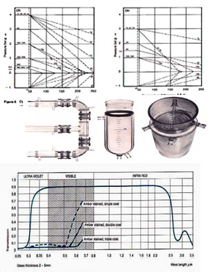
Jacketed components are designed to complement the standard range of glass process plant and pipeline equipment's detailed in this catalogue by extending the range of applications for which glass can be used. Jacketed components, as their name implies, are standard glass components with a glass jacket around them. The jacket is sealed onto the glass component with silicone rubber.

Jacketed components are not only used to avoid heat loss for the purpose of saving energy, but also where the product characteristics have to be maintained to prevent crystallizing or unwanted reactions from occurring. A further area of application is thermal insulation where the ability to still monitor the process visually is a major advantage.

Jacketed versions of all the major glass components detailed in this catalogue are available. The range therefore includes pipeline components, valves and vessels as well as a wide variety of column components and heat exchangers.

Permissible Operating Conditions

For the inner part of jacketed components, the permissible operating pressure are identical to those for their non-jacketed counterparts. These pressures are detailed in the previous pages of this 
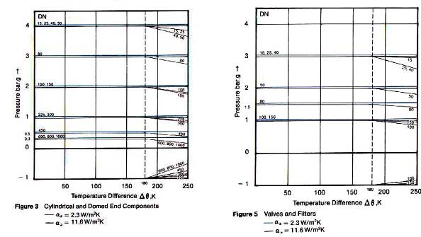
section.

However, deviations will arise in the permissible operating temperature for the inner component and the permissible operating conditions in the jacket itself. These are due to permanently flexible silicone seal, which absorbs the different expansion levels of the inner component and jacket.

Permissible Operating Temperature  

The permissible operating temperature for the inner component is -40°C to +_150°C. For  the jacket it is -40°C to +130°C.

In special circumstances, the operating temperature can be increased to +170°C for the inner component and +150°C in the jacket.

Permissible Operating Pressure

The  permissible  operating  pressure in the jacket is –0.2bar.g to + 0.1bar.g, unless lower values are derived from Figure 3 to 8 on the previous pages.

Please Note:

If there is a vacuum in the jacket, care must be taken to ensure that the pressure difference between the inner component and the jacket does not exceed the permissible operating pressure for given Figure 3 to 8 on the previous pages.

TOP 

Copyrights Reserved 2001-2007 by Garg Scientific Glass Industries.